Subsections of Technique
Scale preparation
With belly-harriers the species classification is traditionally done by the shape of the scales. Therefore, species identification is often only possible if one can accurately assess the scale shape of the animals. Unfortunately, the scales of gastrotrichs are often difficult to see. Even with DIC - although here the weak birefringence of the scales further enhances the contrast - live observation is not sufficient for species diagnosis in many species. Therefore I would like to present here a possibility for the preparation of the scales and thus for the (mostly) safe species diagnosis.
As an example I have chosen
Lepidochaetus zelinkai
. Due to the distinctive appearance of this gastrotrich, a scale analysis for species identification is actually not necessary, but some scale details are controversially discussed in the literature, so I wanted to make up my own mind.
L. zelinkai is a medium sized gastrotrich with a distinctive spiny coat:
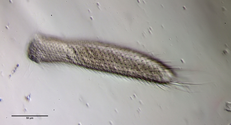
L. zelinkai
: Overview
Even with higher magnification not all details of the scaling become clear:
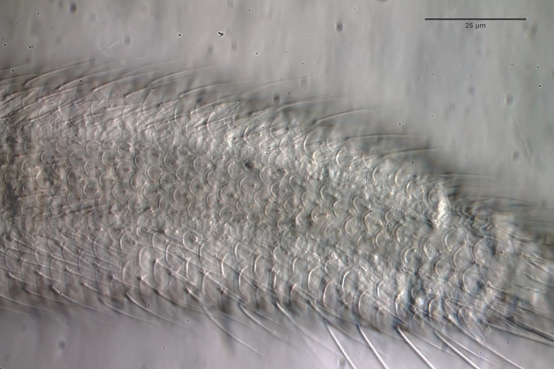
L. zelinkai
: Scales of the ventral interfield
To prepare the scales free, the animal must be macerated. To do this, fix the animal - preferably with a simple Vaseline copressorium - with the coverslip and draw a drop of glacial acetic acid under the coverslip. I stained the glacial acetic acid in advance with very little eosin - this stains the scales at the same time as maceration. The glacial acetic acid dissolves all soft parts of the animal within a few minutes, while the scales of the gastrotrichs are acid-resistant and therefore remain intact. Depending on the scale structure, the scales remain as a cohesive shell or separate from each other. In L. zelinkai , the scales are apparently not interlocked, so the scales disperse:
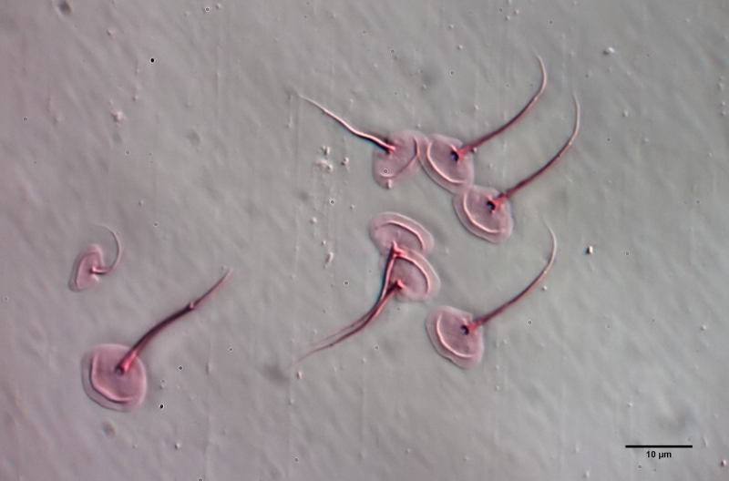
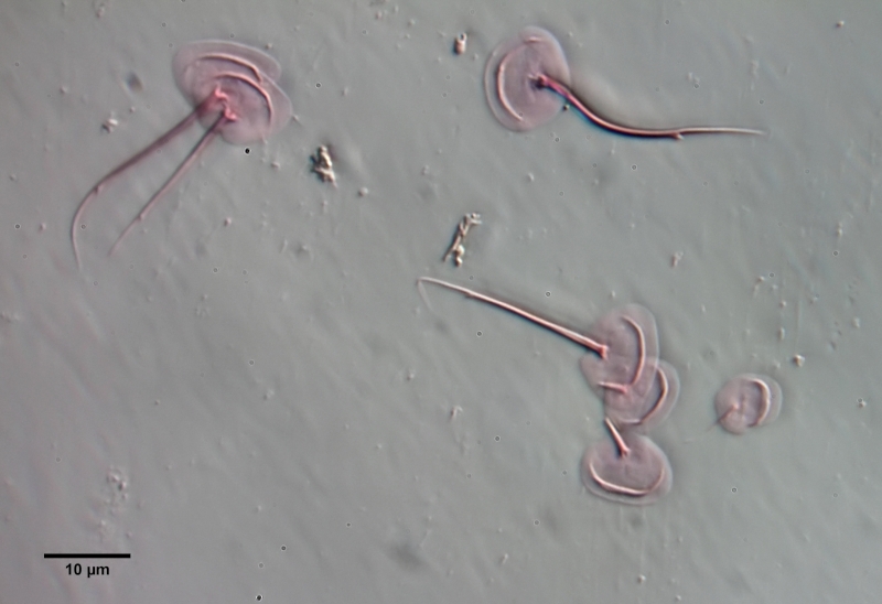
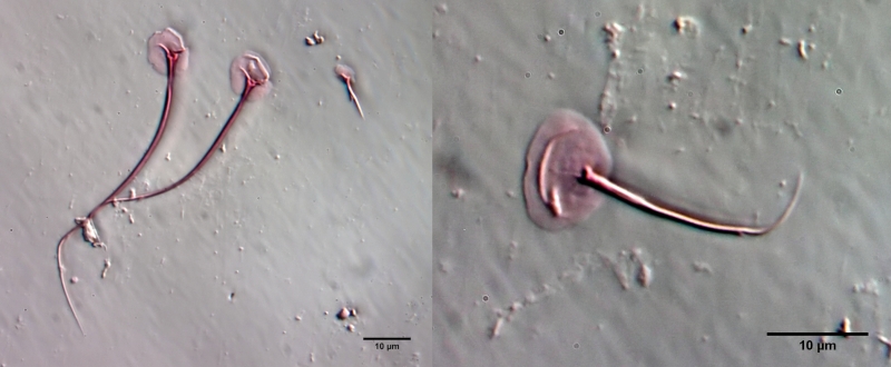
This type of preparation is quite simple and allows the scale shapes to be accurately assessed. For example, in the above images, the ridges in the scale surface that extend parallel to the leading edge are noticeable. In the literature, these “double edges” of the scales are usually considered to be an optical artifact produced by the double intersection of the focal plane through the curved scales. The above scale analysis clearly proves that these conspicuous ridges really exist and represent a thickening of the scales.
Microaquarium
By microaquaria I mean slide-sized preparations that can be observed directly with a microscope. The optical quality of the microaquaria (especially the thickness of the slides) should be good enough to use any possible magnification. In addition, the life span of the organisms inside should be at least a few weeks to be able to study the behavior or development of the objects. Last but not least, the method must be easy and fast to use - a cumbersome method that requires a lot of equipment is not practical in my eyes in the amateur field.
A few years ago I came across a preparation method on the Internet, which I was able to develop into a long-term microaquarium. Such a microaquarium is constructed as follows:
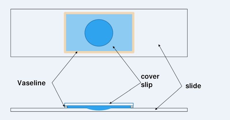
Construction of a microaquarium
The life of a “normal” temporary wet preparation can be increased by effectively preventing the water from evaporating. This can be accomplished by sealing the cover glass with a Vaseline rim to make it watertight. Vaseline has a number of ideal properties for this purpose:
- it is absolutely waterproof
- Vaseline is permeable to air (known from Vaseline-based moisturizers)
- Vaseline is easy to apply due to its consistency
- it can be found inexpensively in every drugstore
To apply a Vaseline edge to the coverslip, apply a thin (!) film of Vaseline to the heel of your hand and wipe a thin ridge off the skin with each coverslip edge. The coverslip can then be placed directly on the slide (with specimen) with one edge. From this edge, lower the coverslip and slowly press the coverslip to the desired thickness using a wooden stick. Excess water is thus pressed out from under the coverslip and can then be easily removed.
To create a long-lasting microaquarium, it is necessary to include a relatively large amount of water in the preparation. If this water buffer is too small, the organisms would die after a few days. Therefore, a microscope slide with a hollow section is used for a microaquarium. To increase the area that can be used for observation, I use a coverslip that is as large as possible (e.g. 24mm x 32 mm or 24mm x 60mm). This maximizes the area outside the hollow grounded section - the area with the optimal slice thickness.
A microaquarium created this way has many advantages:
- Lifespan of organisms up to 6 weeks
- great mechanical stability:
- cleaning is easy due to the fixed cover glass
- vertical storage in normal preparation boxes (transparent cover!)
- absolutely stable conditions also for long-term video recordings
- Use of immersion oil is unproblematic: cover does not slip, oil does not penetrate under the cover glass
- additional effort for preparation only a few hand movements
But the main advantage in my eyes is that the organisms behave “naturally” after an acclimatization period of about one day in the micro aquaria. The typical great restlessness known from the “normal” temporary wet preparations has subsided and the enclosed animals go about their “daily business”. Most ciliates calmly graze their food or even stand in the same spot for hours, swirling their food in a relaxed manner. Gastrotrichs calm down and emerge from their hiding places after some time and graze - optimally observable - the underside of the cover glass.
To demonstrate these relaxed conditions in a microaquarium, I would like to show the following - almost unedited film - taken in several microaquariums a few days after their creation:
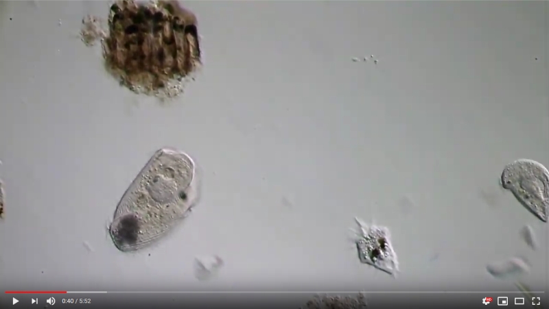
Please click on the picture to start the movie!
For me this kind of preparation is meanwhile the most satisfying way to observe the wonder world in the pond. Of course it is not possible to show the last anatomical details of the organisms. But you get the possibility to observe the behavior or the development of the organisms over a long period of time and without stress.
Coverslip Compressorum
To observe living gastrotrichs in detail microscopically, it is necessary,
- to minimize the slice thickness, as this is the only way to ensure optimal optical conditions for objectives with high magnifications
- to keep the animals immobile
- to minimize the drying of the specimens to the extent that a comfortable observation time can be achieved
- prevent the penetration of immersion oil into the specimen
For this purpose I have developed the coverslip compressorum, which allows to achieve these conditions very easily and quickly.
First, as always, it is necessary to isolate the observation object with a thin pipette under the stereo microscope and apply it to a cleaned slide with as small a drop of water as possible. Care should be taken to ensure that the water droplet is small enough so that the layer of water under the coverslip to be applied does not reach the edges of the coverslip at the desired thickness. Some experience is required for this…

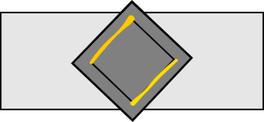
Coverglass compressorium: vaseline bars in yellow.
Some vaseline is rubbed on the heel of a hand. With the upper and lower edge of a rectangular cover slip (I usually use the size 18x18mm) one strips a thin bar of vaseline from the ball of the hand. The vaseline serves as a spacer around the edge of the cover glass. The coverslip is placed on the slide with one edge at an angle - the Vaseline holds the coverslip in this position. Using a small wooden stick, the protruding edge of the coverslip is carefully pressed towards the slide until it reaches the water drop and also rests with the upper side on the slide. The water drop now fills a small section of the coverslip with a relatively large layer thickness.
In this state, the gastrotrich trapped in the water droplet is still free to move and can be conveniently observed with weaker objectives. The small area of the water drop makes it easy to find the object.
Under microscope control, the layer thickness of the water can now be carefully reduced by pressing the coverslip edges just enough so that the gastrotrich is no longer movable and is gently pressed through the coverslip onto the slide. The two Vaseline edges provide sufficient resistance to manual pressure to reduce the coating thickness in a very controlled manner. The two opposing Vaseline edges ensure that
- drying of the preparation is greatly delayed, since evaporation of the water only occurs on the exposed coverslip edges without Vaseline and is therefore reduced.
- the adjusted layer thickness remains almost unchanged when the preparation dries out, since the water drop evaporates only at the edges and only its diameter changes.
- penetration of immersion oil is impossible at the sealed coverglass edges, and there is usually no contact with the sample water at the exposed ones.
- a “pull-through” of chemicals for dyeing etc. is possible without problems because of the open cover glass edges on the opposite side.
- a later manual reduction of the layer thickness until the object is flattened (e.g. for scale analysis is possible at any time in a controlled manner.
With a little experience, the creation of a cover glass compressorum is easy and possible within a few seconds.
I have been using this preparation method for high-resolution observations for years and would not want to do without it!
Double Coverslip
Gastrotrichs are animals in which the upper and lower sides differ greatly. It is often necessary to observe both the ventral and dorsal sides closely. When observing an animal with a coverglass compressorium, usually only one side can be observed accurately. The other side is only accessible when focusing through the animal. However, this results in great optical quality losses - especially with high-resolution lenses. One can then only try to rotate the animal by moving the cover glass. Unfortunately, this method only has a chance of success with round objects and usually ends lethally with gastrotrichs… :cry:
diagonal double cover glass vaseline bridge in yellow
To allow bilateral observation, one can enclose the object between two coverslips and turn the entire coverslip stack on the slide if needed. To do this, use two different sized coverslips. The larger coverslip (e.g., 20x20 mm) is pinned to a slide with a small drop of distilled water. The coverslip should be oriented diagonally so that it can be easily grasped at the opposite corners if necessary. A second, smaller coverslip (18x18 mm) is fitted with a vaseline ridge on two edges (as described in the article coverslip compressor and pressed onto the lower coverslip with the sample in a controlled manner, thus holding the object between the two coverslips.
The object can now be observed with the usual optical quality on the top side. Once observation from this side is complete, a drop of immersion oil is placed on the coverslip (if not already done) and the coverslip stack is detached from the slide at the protruding corners. The stack is rotated and placed with the oiled side on the slide. Now the observation can be made from the now upper, former bottom side. The use of different coverslip sizes ensures that only one coverslip is touched when the coverslip stack is rotated and that the coverslips do not shift against each other.
Equipment
Subsections of Equipment
Lateral stereo microscope illumination
One of the main problems in the preparation of gastrotriches is to track down the animals in a water sample and pipettate on an object carrier.Since gastrotriches are transparent, they are almost invisible in a stereo microscope with traditional incident or transmitted light illumination.The animals only become visible when the field lighting is dark.
In the professional area, dark field lighting is realized by cold light conductor. LED lights with swan neck offer an alternative option that illuminate the sample on the side.This lateral lighting only gets the light spread on the objects into the lens of the microscope.The background remains pure black.Since the lamps are not attached to the sample, the illuminance and the shadow throw changes depending on the sample position.Often the lamps also represent a mechanical obstacle when shifting the sample vessel. This type of lighting is usually not available in stereo microscopes and must be retrofitted.
In order to minimize these disadvantages, I have developed a side dark field lighting for this purpose, which can be easily realized with simple means and a 3D printer and can be adapted to any stereo microscope.
Holder for LED strips
Rotatable object guide
To align slides according to the DIC gradient or the image edges of the camera, it is necessary to rotate the slides on the stage. If you - like me - do not have a rotation stage at your disposal, you have to come up with something…
I have constructed a rotatable object guide, which can easily be manufactured with a simple 3D printer. The following properties were taken into account:
- low height - thus collisions with the objectives are excluded
- mounted to the stage, so that the specimens can still be moved
- specimen rests directly on the stage - no problem with focusing the condenser / Köhler is possible
- easy insertion and removal of the slide
- different dimensions of the slides possible due to spring holder
- insertion of the commercially available plastic Petri dishes with 7 cm diameter possible; additional circular recess for the use of the lids of the Petri dishes (whose height is somewhat smaller, so that no collision with the 10 objective can occur)
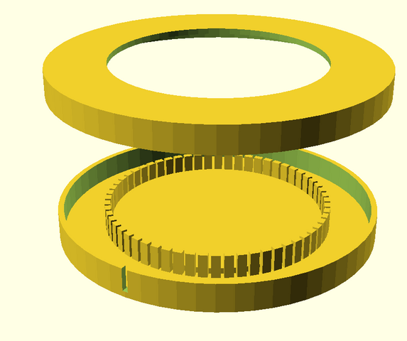
The object guide consists of two separate parts:
- a rotating frame which is fixed to the stage with the usual fixing screws
- a turntable which is placed in the frame and can be rotated in it. To facilitate the rotation, the turntable rests on the frame only at six points. The turntable is equipped with six handles so that it can be easily operated from all sides
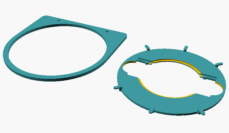
Fig. 1: Individual parts of the specimen guide; on the left, frame that is mounted to the stage; on the right, the turntable that holds the slide or Petri dish.
The two parts are inserted into each other. The slide sits firmly in the recess and can be rotated 360 degrees and oriented as desired. The round recesses are provided for Petri dishes, if necessary.
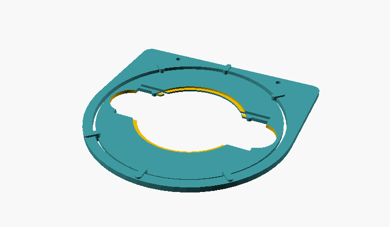
Fig. 2: assembled object guide
At the microscope the whole thing looks like this:
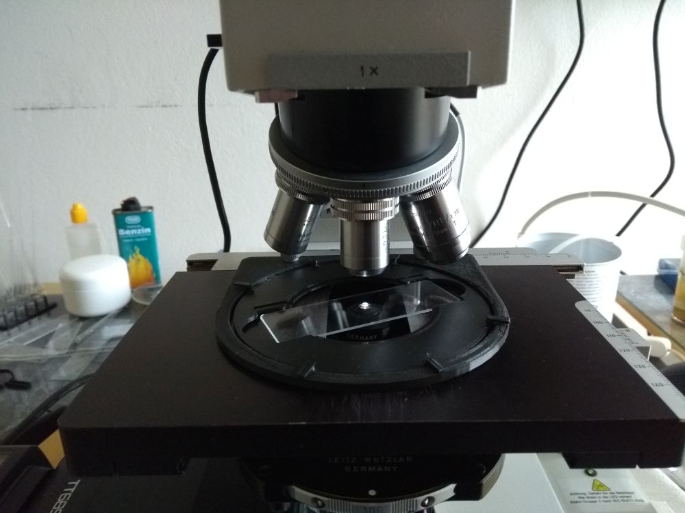
Fig. 3: Rotatable object guide on microscope
This design has proven itself in practice. Of course, the rotary stage cannot be centered when rotating, the position of the specimen must be readjusted by the stage. The slides fit tightly enough so that there is no “slippage” at all when moving them. However, some slide marks seem to have a slightly smaller depth, so one wishes they would sit a little tighter on those. If you want to use such slides, you have to adjust the retaining springs a bit….
The corresponding print files - including the CAD files in OpenSCad format can be downloaded from Thingiverse. The design is adapted to the stage of my Ortholux II. For other microscopes, the position or diameter of the holding screws may have to be adjusted.
I would not like to miss this practical object guide anymore. Only by rotating the object to the optimal angle is it possible to achieve, for example, optimal contrasting with DIK. Also the alignment at the photo edges saves the constant turning of the camera.
Flash Light
Dhe advantages and disadvantages of a microflash setup on the microscope have already been discussed in detail in several articles. For me as a “Enthusiast of the Pond”, the decisive factor was that a microflash
- allows to observe with minimal light intensity (of the pilot light). Unfortunately, there are many organisms that do not tolerate well the often high light levels required for DIC and panic to avoid the light or even do not survive the illumination.
- ensures a constant white balance of the photos independent of the light intensity of the pilot light.
- allows short exposure times independent of the pilot light. If one wants to realize short exposure times with the “normal” LED illumination, one typically has to set the lamp to maximum light intensity before releasing the shutter, but this is uncomfortable for observation. This is the only way to then achieve exposure times shorter than 1/500 s, which is necessary to “freeze” the motion blur.
- Motion blur minimized with typical exposition times of less than 1/2000 at ISO 100. With LED lighting, I typically achieve only 1/200 s at 100 DIK at ISO 400.
That’s why I constructed flash equipment for my Ortholux II with my 3D printer!
With a microflash, in principle, you have the fairly simple option of mirroring the flash to the side under the condenser. However, such a setup is rather provisional, since during “normal operation” the flash and beam splitter under the object stage interfere and limit the ergonomic operation. For a permanently attached microflash on a microscope with a separate lamp house, the “flash cubes” have proven themselves. They are inserted between the lamp house and the stand and here reflect the flash into the “normal” beam path. This also allows flash illumination under “Köhler condition”, since the existing light field diaphragm is also used for the flash. So it had to become a similar flash cube solution, where the necessary mechanical components should be created with a 3D printer. My solution looks like this:
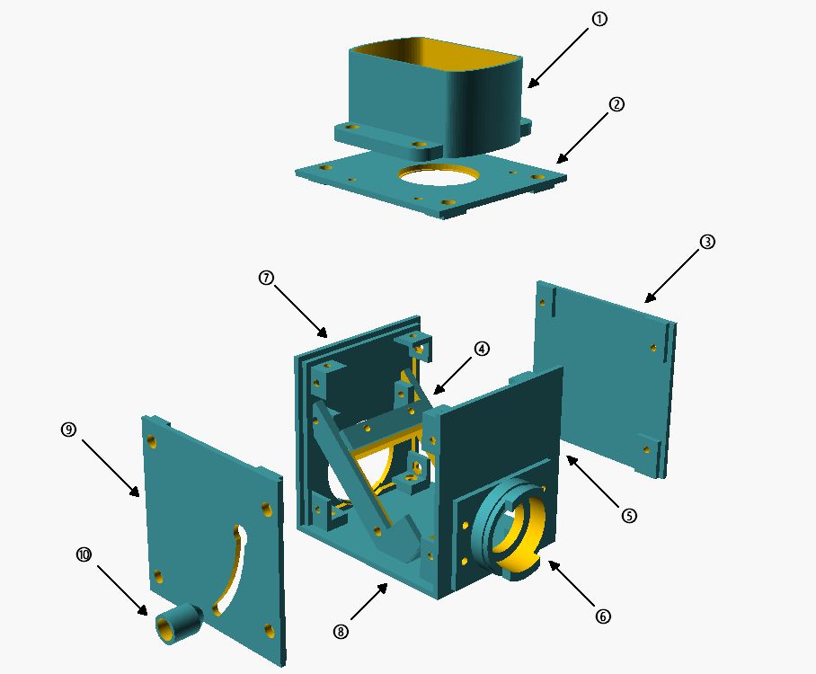
Exploded view of flash cube: 1: flash holder; 2: cover; 3: side wall; 4: rotating beam splitter holder; 5: wall side; 6: lamp bayonet microscope side; 7: lamp bayonet lamp side; 8: bottom plate; 9: side wall with swivel handle; 10: spring-loaded handle.
The central component is the beam splitter holder (4), which would be designed to swivel. This makes it possible to remove the beam splitter from the beam path and also to operate the illumination beam path without interference from the flash. To ensure a secure hold of the swung-out beam splitter, the swivel handle (10) was also attached to the swivel axis with a spring, so that it presses against the side wall and locks into the recess in the upper position. To swivel in the beam splitter, the handle must be pulled outward to allow free movement. On the lamp and stand side, the cube walls (6 and 7) were designed according to the dimensions for the lamp bayonet on the Ortholux II. This allows the flash cube to be firmly mounted between the lamp and stand and does not further interfere with the operation of the microscope. The light aperture (2) on the lid of the flash cube has been adapted to the dimensions of the collector lens so that it can simply be inserted directly. Therefore, when transporting, the collector lens should be removed, as it is held in place only by gravity. Due to this construction, the flash sits directly on the collector lens and the distance to the flash tube is almost optimal. The Fresnel plate of the flash cannot cause any interference in the image, as it sits very close to the collector lens and is therefore not in focus. A holder (1) for the flash is screwed onto the top, which is of course adapted to the dimensions of the flash unit used.
Assembled, the whole thing looks like this:

overall view
The outer dimensions (without flash holder) of the flash cube are 90mm * 100mm * 105mm - so it is actually a “flash cuboid”. These dimensions are due to the dimensions of the purchased parts (beam splitter, collector lens, flash) and the specifications of the lamp bayonet. In reality at the microscope, the microflash device looks like this:
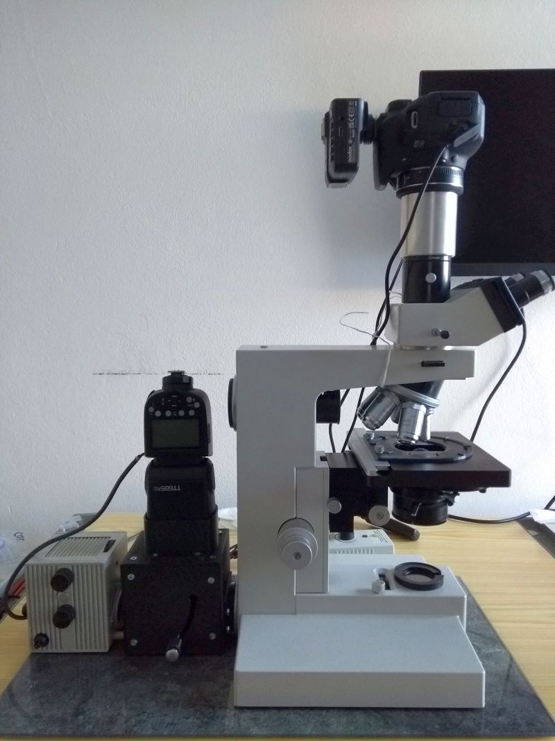
Flash on Ortholux II
As a flash I use a Godox TT685II for Canon cameras with wireless remote control, which works without problems with my EOS700D. The flash has a guide number of 60 and thus enough power to still expose correctly with 1/8 of the maximum power at the 100 DIC. I operate the flash in TTL mode, which easily adjusts the flash power to the subject / lens. Only an exposure compensation of -1.7 EV had to be set. This exposure compensation is independent of the lens used, but sometimes needs to be adjusted to the subject - just like with normal photos. To operate the flash with a power supply, I replaced the batteries with battery dummies, to which a 6V power supply is connected. For those who want to try a replica, I have put together the corresponding OpenSCAD files here for download. An adaptation to the geometry of other beam splitters, collector lenses and flash units is possible without any problems. More difficult is the adaptation to lamp bayonet microscope manufacturers. This is possible in principle, but may require changes to the beam delivery, as the position of the light axis may then change. If you have problems, just ask - everything is possible somehow…
I am very satisfied with this microflash solution and would not want to miss it anymore. Unfortunately, this eliminates another excuse for my photo quality - now I guess I have to learn how to take good photos after all…