
Flash Light
Dhe advantages and disadvantages of a microflash setup on the microscope have already been discussed in detail in several articles. For me as a “Enthusiast of the Pond”, the decisive factor was that a microflash
- allows to observe with minimal light intensity (of the pilot light). Unfortunately, there are many organisms that do not tolerate well the often high light levels required for DIC and panic to avoid the light or even do not survive the illumination.
- ensures a constant white balance of the photos independent of the light intensity of the pilot light.
- allows short exposure times independent of the pilot light. If one wants to realize short exposure times with the “normal” LED illumination, one typically has to set the lamp to maximum light intensity before releasing the shutter, but this is uncomfortable for observation. This is the only way to then achieve exposure times shorter than 1/500 s, which is necessary to “freeze” the motion blur.
- Motion blur minimized with typical exposition times of less than 1/2000 at ISO 100. With LED lighting, I typically achieve only 1/200 s at 100 DIK at ISO 400.
That’s why I constructed flash equipment for my Ortholux II with my 3D printer!
With a microflash, in principle, you have the fairly simple option of mirroring the flash to the side under the condenser. However, such a setup is rather provisional, since during “normal operation” the flash and beam splitter under the object stage interfere and limit the ergonomic operation. For a permanently attached microflash on a microscope with a separate lamp house, the “flash cubes” have proven themselves. They are inserted between the lamp house and the stand and here reflect the flash into the “normal” beam path. This also allows flash illumination under “Köhler condition”, since the existing light field diaphragm is also used for the flash. So it had to become a similar flash cube solution, where the necessary mechanical components should be created with a 3D printer. My solution looks like this:
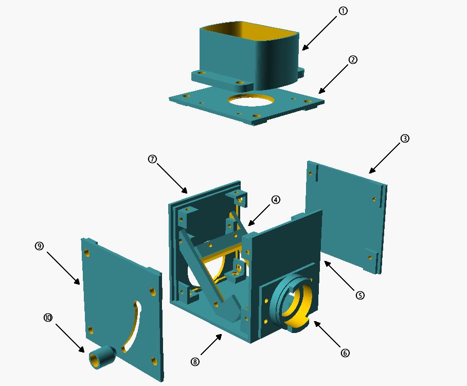
Exploded view of flash cube: 1: flash holder; 2: cover; 3: side wall; 4: rotating beam splitter holder; 5: wall side; 6: lamp bayonet microscope side; 7: lamp bayonet lamp side; 8: bottom plate; 9: side wall with swivel handle; 10: spring-loaded handle.
The central component is the beam splitter holder (4), which would be designed to swivel. This makes it possible to remove the beam splitter from the beam path and also to operate the illumination beam path without interference from the flash. To ensure a secure hold of the swung-out beam splitter, the swivel handle (10) was also attached to the swivel axis with a spring, so that it presses against the side wall and locks into the recess in the upper position. To swivel in the beam splitter, the handle must be pulled outward to allow free movement. On the lamp and stand side, the cube walls (6 and 7) were designed according to the dimensions for the lamp bayonet on the Ortholux II. This allows the flash cube to be firmly mounted between the lamp and stand and does not further interfere with the operation of the microscope. The light aperture (2) on the lid of the flash cube has been adapted to the dimensions of the collector lens so that it can simply be inserted directly. Therefore, when transporting, the collector lens should be removed, as it is held in place only by gravity. Due to this construction, the flash sits directly on the collector lens and the distance to the flash tube is almost optimal. The Fresnel plate of the flash cannot cause any interference in the image, as it sits very close to the collector lens and is therefore not in focus. A holder (1) for the flash is screwed onto the top, which is of course adapted to the dimensions of the flash unit used.
Assembled, the whole thing looks like this:

overall view
The outer dimensions (without flash holder) of the flash cube are 90mm * 100mm * 105mm - so it is actually a “flash cuboid”. These dimensions are due to the dimensions of the purchased parts (beam splitter, collector lens, flash) and the specifications of the lamp bayonet. In reality at the microscope, the microflash device looks like this:
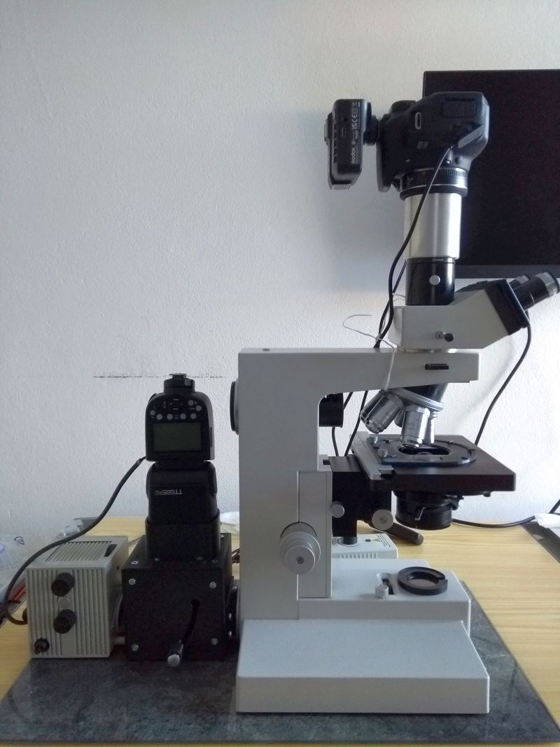
Flash on Ortholux II
As a flash I use a Godox TT685II for Canon cameras with wireless remote control, which works without problems with my EOS700D. The flash has a guide number of 60 and thus enough power to still expose correctly with 1/8 of the maximum power at the 100 DIC. I operate the flash in TTL mode, which easily adjusts the flash power to the subject / lens. Only an exposure compensation of -1.7 EV had to be set. This exposure compensation is independent of the lens used, but sometimes needs to be adjusted to the subject - just like with normal photos. To operate the flash with a power supply, I replaced the batteries with battery dummies, to which a 6V power supply is connected. For those who want to try a replica, I have put together the corresponding OpenSCAD files here for download. An adaptation to the geometry of other beam splitters, collector lenses and flash units is possible without any problems. More difficult is the adaptation to lamp bayonet microscope manufacturers. This is possible in principle, but may require changes to the beam delivery, as the position of the light axis may then change. If you have problems, just ask - everything is possible somehow…
I am very satisfied with this microflash solution and would not want to miss it anymore. Unfortunately, this eliminates another excuse for my photo quality - now I guess I have to learn how to take good photos after all…